

『Turbine flowmeter specifications』Related information(flow rotameter|digital flow meter|balo meter|hydraulic flow meter|volumetric meter|positive displacement meter|pitot tube flow meter|displacement meter|cfm meter|variable area flow meter|inline flow meter|differential pressure flow meter|calibrated flow meter|velocity meter|paddle wheel flow meter|oval gear flow meter|anemometer hvac|multiphase flow meter|doppler flow meter|thorpe tube flowmeter|heat flow meter)

1. Measurement range of liquid turbine flowmeter
Instrument diameter (mm) Normal flow range (m3/h) Extended flow range (m3/h) Conventional connection method and pressure resistance grade Special pressure resistance grade (MPa) (stupid sensitive flange connection method) DN 4 0.04-0.25 0.04-0.4 threaded connection/6.3MPa
10, 1
6, 25 DN 6 0.1-0.6 0.06-0.6 threaded connection/6.3MPa
10, 1
6, 25 DN 10 0.2-1.2 0.15-1.5 threaded connection/6.3MPa
10, 16. 25 DN 15 0.6-6 0.4-8 threaded connection/6.3MPa 4.0. 6.3. 1
2. 1
6. 25 DN 20 0.8-8 0.45-9 threaded connection/6.3MPa 4.0. 6.
3. 1
2. 1
6. 25 flange connection DN 25 1-10 0.5-10 threaded connection/6.3 MPa 4.0、6.
3、1
2、1
6、 25 flange connection/2.5MPa DN 32 1.5~15 0.8~15 threaded connection/6.3 MPa 4.0、6.
3、1
2、1
6、 25 flange connection/2.5MPa strip branch DN 40 2-20 1-20 threaded connection/6.3MPa 4.0, 6.
3, 1
2, 1
6, 25 flange connection/2.5MPa DN 50 4-40 2-40 flange connection/2.5MPa 4.0, 6.
3, 1
2, 1
6, 25 DN 65 7-70 4-70 flange connection/2.5MPa 4.0, 6.
3, 1
2, 1
6, 25 DN 80 10-100 5~100 flange connection/2.5 MPa 4.0、6.3、1
2、1
6、25 DN 100 20~200 10~200 Flange connection/2.5 MPa 4.0、6.
3、1
2、1
6、25 DN 125 25~250 13~250 Flange connection/1.6 MPa 2.
5、4.0、6.
3、1
2、16 DN 150 30~300 15~300 Flange connection/1.6 MPa 2.
5、4.0、6.
3、1
2、16 DN 200 80~800 40~800 Flange connection/1.6MPa 2.
5, 4.0, 6.
3, 1
2, 16
2. Installation suggestions for the front and rear straight pipe sections of the turb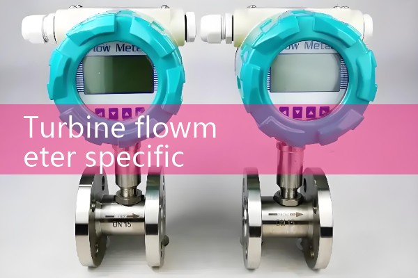
Installation suggestions for the front and rear straight pipe sections of the turbine flowmeter The length of the front and rear straight pipe sections of the turbine flowmeter is crucial to ensure that the fluid forms a stable flow state before and after passing through the flowmeter, which directly affects the accuracy and reliability of the measurement. The following are installation suggestions for the front and rear straight pipe sections based on the specifications, manufacturer recommendations, and standard specifications of the turbine flowmeter:
1. The length of the front straight pipe section (upstream straight pipe section) is generally recommended to be 10 to 20 times the inner diameter of the pipeline (D). The setting of this length aims to ensure that the fluid is sufficiently stable before entering the turbine flowmeter and eliminate the possible impact of fluid turbulence or eddies on the measurement. Specifically, fluid stability: A sufficiently long straight pipe section can ensure that the fluid reaches a stable state before flowing into the flowmeter, reducing measurement errors caused by uneven fluid velocity distribution or eddies. Eliminating interference: By increasing the length of the front straight pipe section, it is possible to effectively eliminate the interference of bends, valves, and other components in the upstream pipeline on the fluid flow state, ensuring that the fluid enters the flowmeter in a stable state. Secondly, the length of the downstream straight pipe section is generally recommended to be 5 to 10 times the inner diameter of the pipeline (D). The setting of this length aims to ensure that the fluid can return to a stable state after flowing through
 Hot Blog
 Related AD